Pneumatic systems
employ gas (or air) that is compressed under extremely high
pressure. The practical use of pneumatics comes in
putting that compressed gas to use, or should I say the use
of the rapid expansion of compressed gas. At its most basic
level
a pneumatic system holds compressed gas in a specially
designed tank and then we release some of that gas into an
expandable
chamber. The expandable part of the chamber has a rod
attached to it so that as it expands the rod moves outward.
Sounds
pretty simple, right? Well, in theory it is, but it is in
application that things get complicated.
Now lets get familiar with the parts commonly used in
pneumatics
1.Fluid:
The first part of a pneumatic
system may not sound like an actual part, but the main and
is called the compressed gas
or AIR itself.
2.Tank:
The second part of a
pneumatics system is the compressed gas storage, otherwise
known as the tank. Tanks range in size,
weight, and proofs (rated capacities) depending upon their
use. Tanks should be DOT-approved and can be made of steel
or
Carbon Filament wound Aluminum (like wrapping it with carbon
fiber) and will either have the working pressure in psi
stamped
into the tank or will have a certification sticker on it.
Tanks may also be measured in "bar" (not plural). 1 Bar is
equivalent to about 14.5 psi which is equivalent to 100KPA
which is equivalent to 1 Atmosphere. So a 69 bar tank is
equivalent to 1000 psi.
Each tank should also have a
burst valve to keep the tank from excessive pressure. In
general the burst valve is rated
for 120% of the tanks normal operating capacity. If the
pressure builds to above 120% of the rated pressure the
burst valve
will pop open and vent the gas slowly to prevent the tank
from exploding. Tanks are generally hydro-tested to twice
the rated
capacity to pass DOT-approval inspection. Common sources of
tanks are welding supply shops, diving shops, paintball
stores,
and even fire extinguisher tanks!
3.Regulators:
Regulators are interesting
pieces of hardware in that they can hold back 5000 psi of
air and let only a enough air
through to bring the rest of the pneumatic system up to your
designed operating pressure. Regulators also generally have
a
purge valve to allow you to purge all of the air out of a
pressurized tank.
4.Buffer Tank:
Buffer tanks are not
necessarily part of every pneumatic system. But, if you have
the extra weight allowance and space
available they are very handy to have. A buffer tank is just
an extra tank in between your regulator and your valve that
stores extra gas. So, what does that do for us?
Let's say that you have a pneumatic cylinder that has a 4
inch bore and a 6 inch stroke. That gives us a total of
about
75 cubic inches. Now, let's say that you are using 1/2"
pneumatic tubing between your regulator and your valve and
on to the
cylinder and we are using 250 psi of gas. If you have 24" of
total tubing you have almost 5 cubic inches of compressed
air in
the feed lines. That will move the piston about half an inch
before the regulator has to start feeding more air into
chamber.
The second the pressure in the feed lines drop below the
regulated pressure the regulator starts letting more air
through.
But what if you have a regulator and is not a high flow
kind? Well then your high powered pneumatic flipper just
turned into
a lifter.
Now, let's put a 75 CI buffer tank in line before the valve.
This time the regulator spends a little longer initially
filling the feed lines and the buffer tank. But, when you
fire the valves the buffer tank dumps its 75 cubic inches of
compressed gas along with the 5 that was already in the
lines. This time there is a lot more pressure immediately
available
to the cylinder and we get the "pop" that we are looking for
in a flipper.
5.Pneumatic
hoses and fittings:
Well, for all of the air to move around we need to have a
way to move it. That's where the hoses and fittings come
into
play. To get the best air flow you need to use the largest
diameter hose that you can find that is rated for the
pressures
that you will be using. You will also need to find matching
connectors and fittings throughout the system. It does no
good to
have 1/2" hoses and fittings throughout your whole system
only to have a 1/8" port on your solenoid valves (okay, so
it's an
extreme example but you get my drift). The 'push to connect'
low pressure fittings and hoses are the easiest to work with
for
prototyping and low pressures.
You can get pneumatic hoses and fittings that are rated for
very high pressures. You can also use hydraulic lines but
they not really good for moving high volume of air in a
hurry but some will work. Hydraulic lines and fittings are
designed
for extremely high pressure and are sometimes sheathed with
a steel mesh to help keep the hose from deforming and
developing
bubbles.
It is a good idea to use PTFE (Teflon) tape on all threaded
connections as it helps seal any gaps that may occur between
the threads.
6.Valves:
The valve will probably be the
most critical (and consequently the most expensive) part of
a high power pneumatics system. It has to restrain the
pressure built up on one side and be able 'pop' completely
open and not restrict the air as it rushes through on its
way to the cylinder. There are many types of vales that can
be used; Remotely Operated, Manually Operated, and Solenoid
Valves.
For the context of this help section we will just keep it to
solenoid valves.
The reason that it is called a 'solenoid valve' is because
there are really two parts; the valve (and valve body) and
then solenoid that activates the valve. The solenoid opens a
smaller valve that controls a small stream of air that then
pops open the large high flow valve.
There are several different types of solenoid valves but we
are just going to talk about the three most common ones used
in robots. There is a 3-port, a 4-port, and a 5-port
solenoid valve.
The 3-port solenoid valve is so named because it has three
ports; one from the tank, one going to the cylinder, and one
exhaust. Because there is only one going to the cylinder we
will be using a single acting cylinder (It is possible to
use a 3-port valve with a double acting cylinder but that
gets into advanced design and is therefore beyond the scope
of this help section). The valve opens, and pressurizes the
cylinder therefore extended the ram. Then the valve closes
which opens the exhaust port and the gas in the cylinder is
allowed to vent which equalizes it with the outside air and
the ram retracts.
A 4-port valve is designed to be used with a double acting
cylinder. It has four ports; one from the tank, one to the
back of the cylinder, one to the front of the cylinder, and
one shared exhaust. In its normally closed position it
allows pressure to build up on either the front or the back
of the piston depending upon your design. When the valve
activates it redirects the compressed air to the opposite
side of the piston while simultaneously opening the exhaust
port so that the air that is currently in the cylinder can
escape. If the air in the cylinder were not allowed to
escape then it would just build up pressure when the ram
piston tries to move and not allow the piston to go
anywhere.
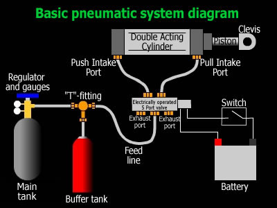
A 5-port valve is also designed to be used with a double
acting cylinder but has an added exhaust port. This
increases the efficiency of air flow leaving the cylinder
which allows it to extend or retract faster. The diagram to
the right in this section shows how a 5-port solenoid valve
works.
7.The Actuator/Cylinder:
The actuator is the business
end of a pneumatics system. All of the parts listed above
are to make the actuator (cylinder) move, and move with
authority. There are three main types of actuators, each
with their own advantages and disadvantages; Single Acting,
Single Acting Spring Return, and Double Acting. Inside the
cylinder is a disc that is sealed against the walls of the
cylinder. Then there is a rod attached to the disc which
extends out one end of the cylinder. The rod is where we
will attach things to to make things move, usually via a
clevis. There are end caps on each end of the cylinder to
keep the piston from shooting out of the cylinder when the
piston slams into it at high speed. Actuators are typically
made out of high grade aluminum or steel (usually the
stainless variety). There are also a variety of mounting
styles.
A single acting cylinder has only one inlet port and
therefore only one power stroke. This is usually at the back
of the cylinder so that the power stroke is the 'push'
stroke. These require some other means of retracting the
piston to its starting position, like gravity. Because of
this standard single acting cylinders have a slow reload
time. On the plus side it only has one inlet and therefore
you get more shots per tank full.
Single acting spring return cylinders are just like the
standard single acting cylinders with the exception that
they have a spring inside of them. At the completion of the
power stroke the spring helps to push the piston back to its
starting position. Like the standard single acting cylinder
this one allows you get more shots per tank full than a
double acting cylinder and it has the added bonus of a
spring return to help speed up reload times. But, alas, it's
not all roses. Because there is a spring inside the cylinder
it will take pressure to compress it which takes away from
power that you could potentially be putting into flipping
the opponent. This is usually a minor issue but the bigger
issue is the fact that single acting spring return cylinders
tend to be longer to accommodate the spring.
The last one is the double acting cylinder. It is called
double acting because it has a power stroke on the push AND
pull. The picture to the left is of a double acting cylinder
and you will notice an inlet port on each end cap.